Popular Posts

Share |

Tuesday, March 23, 2010

802.1d - How the STP functioning ?

Function of Spanning Tree Protocol - 802.1d
At the first I think it's better to have a brief description on STP.

STP is directly responsible for avoid following errors occur in a switched network, where the switches are connected in a loop.

1. Avoid receiving multiple frames of same data to hosts
2. Avoid packets going on an endless loop
3. Make MAC address table steady 

all of above errors are possible to occur in an environment where the STP in not available. STP blocks a selected port on a loop to avoid those errors. The blocking port selected as follows.

STP blocks the designated port of highest cost path bearing switch to the root bridge. Then what are the designated ports and root bridge ?

Bridge ID, BPDU and Root bridge

Every switch has a bridge ID. Bridge ID is a combination of Priority value and lowest MAC address value. Priority value is 32768 by default in catalyst switches and it could be configure manually. The first factor is to consider for bridge ID is priority value. If the value is low, Bridge ID is high. value 1 is the maximum and value 0 is not be consider. If some switches have same priority, then the MAC address will be considered. Lower the MAC address is higher the Bridge ID. 

Scene 1
In every 2 seconds, every switch send a packet named BPDU ( Bridge Protocol Datagram Unit ) which includes details about bridge ID and etc. By BPDU's every switch came to know about all other switch's Bridge IDs and they automatically appointed a leader switch which have the highest Bridge ID ( Highest priority and lowest MAC ). The leader is named as Root bridge.

Scene 2
After appointing a root bridge the switches mark their ports as following
1. Root port - Outgoing port towards the root bridge
2. Designated port - Other ports in the loop except Root port

Scene 3
Calculate the costs of paths as follows
                    old      new
10Gbps                   2
01Gbps        1         4
100Mbps     10       19
10Mbps       100     100

After that the STP blocks the designated port at the port where the highest cost path to the root bridge. Then the loop will no available any more. Remember that the BPDU's can go through blocked port while other packets can't. 

Scene 3 
let's see what will happen when a link to the root port is went down. Remember that the STP can keep a port on 4 modes as follows
1. blocking
2. listening
3. learning
4. forwarding

When a link to the root bridge is down the blocked port have to come up for the proper functioning of the network. Bringing a port to the forwarding mode happen as follows

step 1. when a link is down the switch will not receive anymore BPDU's from that side. In certain cases a switch may miss some BPDUs. because of that switch stay for 20 seconds ( 10 BPDU ) to exactly know whether the link is down. If no any BPDU received from that side for 20 seconds, then the switch know exactly there's a problem.

step 2. After 20 seconds the port will be changed the status in to listening mode. in listening mode, the switch send BPDU's through the blocked port and listen do they come back from the other side. That's to make sure that there will not occur any loops if the blocked port is opened. The port keep on listening mode for 15 seconds and then go to the next step if there's no BPDU receiving from the other side.

step 3. Then the port will change the status to learning mode where the switch learns MAC addresses of network. Stay another 15 seconds on learning mode

step 4. The port will be opened for packets and start forwarding.

like that in STP it takes minimum of 50 seconds to network bring back to functioning. It is a big disadvantage taking so much time to bring the network up and working. All of the above described mode changing activities can be observe in a real switched network or by using Packet tracer with some techniques. For packet tracer users, I can send a simulation file on your request. please leave a comment or send a message via facebook if you need those simulation files.

Tuesday, March 16, 2010

Spanning Tree Protocol - 802.1d

Overview and introduction to Spanning tree protocol
STP is a standard protocol which is works on any brand of switches. ISL ( Inter Switch Link ) is the Cisco proprietary protocol instead of STP. STP cannot be explained alone since it's related with several number of operations on switches such as Bridge ID, BPDU and etc.


Spanning-Tree Protocol (STP) as defined in the IEEE 802.1D is a link management protocol that provides path redundancy while preventing undesirable loops in the network. For an Ethernet network to function properly, only one active path can exist between two stations. Loops occur in networks for a variety of reasons. The most common reason you find loops in networks is the result of a deliberate attempt to provide redundancy - in case one link or switch fails, another link or switch can take over.

STP is a technology that allows bridges to communicate with each other to discover physical loops in the network. The protocol then specifies an algorithm that bridges can use to create a loop-free logical topology. In other words, STP creates a tree structure of loop-free leaves and branches that spans the entire Layer 2 network.

Spanning-Tree Protocol operation is transparent to end stations, which are unaware whether they are connected to a single LAN segment or a switched LAN of multiple segments. Where two bridges are used to interconnect the same two computer network segments, spanning tree is a protocol that allows the bridges to exchange information so that only one of them will handle a given message that is being sent between two computers within the network.

Bridge Protocol Data Units (BPDUs) is used by bridges in a network to exchange information regarding their status. The Spanning-Tree Protocol uses the BPDU information to elect the root switch and root port for the switched network, as well as the root port and designated port for each switched segment.

The program in each bridge that allows it to determine how to use the protocol is known as the spanning tree algorithm, which is specifically constructed to avoid bridge loops. The algorithm is responsible for a bridge using only the most efficient path when faced with multiple paths. If the best path fails, the algorithm recalculates the network and finds the next best route. 
The spanning tree algorithm determines the network (which computer hosts are in which segment) and this data is exchanged using Bridge Protocol Data Units (BPDUs). It is broken down into two steps:

Step 1: The algorithm determines the best message a bridge can send by evaluating the configuration messages it has received and choosing the best option.


Step 2: Once it selects the top message for a particular bridge to send, it compares its choice with possible configuration messages from the non-root-connections it has. If the best option from step 1 isn't better than what it receives from the non-root-connections, it will prune that port. 

Monday, March 15, 2010

Lab commands - VTP configurations

How to Configure VTP and how to view configurations ?
Since you have practiced certain commands and been in touch with cisco devices i assume that i don't need to explain basic commands from here.
As you know by default all the Catalyst switches are on server mode. To view the current mode,
in CLI ( Command Line Interface )
go to privilege mode enter following command.

Switch#show vtp status 
VTP Version                     : 2
Configuration Revision       : 0
Maximum VLANs supported locally : 255
Number of existing VLANs              : 5
VTP Operating Mode                       : Server
VTP Domain Name                          : 
VTP Pruning Mode                          : Disabled
VTP V2 Mode                                : Disabled
VTP Traps Generation                     : Disabled
MD5 digest                      : 0x7D 0x5A 0xA6 0x0E 0x9A 0x72 0xA0 0x3A 
Configuration last modified by 0.0.0.0 at 0-0-00 00:00:00
Local updater ID is 0.0.0.0 (no valid interface found) 

You can see the VTP operating mode is Server and many details which we have to discuss in advance.

Now enter to Global configuration mode and type following commands


Switch(config)#vtp mode client " To change the VTP mode from server to client "
Setting device to VTP CLIENT mode.
Switch(config)#vtp domain cisco " To assign the domain name as cisco "
Changing VTP domain name from NULL to cisco

As i explained in earlier articles, the domain name must be same in all switches which you want to make receive updates from a server switch. That meant when you assign domain name as cisco for one switch in server mode and assign all other client mode switched the sane domain name, All client switches which have domain name as cisco will receive updates from server switch.

Saturday, March 13, 2010

Lab commands - VLAN configurations

Lab commands - VLAN configurations


Switch#enable "enter to privilage mode"


Switch#configure terminal  "Enter to Global configuration mode"


Enter configuration commands, one per line.  End with CNTL/Z.


Switch(config)#interface vlan 1 "Go to interface mode of VLAN 1"


Switch(config-if)#ip address 10.1.1.1 255.255.255.0 "Assign IP address for interface VLAN 1 with the subnet mask"


Switch(config-if)#no shutdown "make the interface up"


%LINK-5-CHANGED: Interface Vlan1, changed state to up
Switch(config-if)#
%SYS-5-CONFIG_I: Configured from console by console
Switch#


VIEW CONFIGURATIONS


Switch#show interfaces VLAN 1 "Show details of  interface VLAN 1"
Vlan1 is up, line protocol is down "Both vlan1 and line protocol must be up for working condition"


Hardware is CPU Interface, address is 0010.1116.ce76 (bia 0010.1116.ce76)
  Internet address is 10.1.1.1/24
  MTU 1500 bytes, BW 100000 Kbit, DLY 1000000 usec,
  reliability 255/255, txload 1/255, rxload 1/255
  Encapsulation ARPA, loopback not set
  ARP type: ARPA, ARP Timeout 04:00:00
  Last input 21:40:21, output never, output hang never
  Last clearing of "show interface" counters never
  Input queue: 0/75/0/0 (size/max/drops/flushes); Total output drops: 0
  Queueing strategy: fifo
  Output queue: 0/40 (size/max)
  5 minute input rate 0 bits/sec, 0 packets/sec
  5 minute output rate 0 bits/sec, 0 packets/sec
     1682 packets input, 530955 bytes, 0 no buffer
     Received 0 broadcasts (0 IP multicast)
     0 runts, 0 giants, 0 throttles
     0 input errors, 0 CRC, 0 frame, 0 overrun, 0 ignored
     563859 packets output, 0 bytes, 0 underruns
     0 output errors, 23 interface resets
     0 output buffer failures, 0 output buffers swapped out


Switch#SHOW running-config "view running configurations of interface VLAN 1"

!
interface Vlan1
 ip address 10.1.1.1 255.255.255.0
!

Friday, March 12, 2010

Test Inside 640-802 (CCNA Exam Simulator)

DOWNLOAD NOW FOR FREE....
“CCNA ’s Cisco Certified Network Associate”, also known as 640-802 exam, is a Cisco certification. Preparing for the 640-802 exam? Searching 640-802 Test Questions, 640-802 Practice Exam, 640-802 Dumps? With the complete collection of questions and answers, TestInside has assembled to take you through 252 questions to your 640-802 Exam preparation. In the 640-802 exam resources, you will cover every field and category in CCNA helping to ready you for your successful Cisco Certification.


Password - careercert.blogspot.com

Thursday, March 11, 2010

VTP ( VLAN Trunking Protocol) - 802.1Q

VTP ( VLAN Trunking Protocol) - 802.1Q


VLAN Trunking Protocol (VTP) is a Cisco Layer 2 messaging protocol that manages the addition, deletion, and renaming of VLANs on a network-wide basis. Virtual Local Area Network (VLAN) Trunk Protocol (VTP) reduces administration in a switched network. When you configure a new VLAN on one VTP server, the VLAN is distributed through all switches in the domain. This reduces the need to configure the same VLAN everywhere. VTP is a Cisco-proprietary protocol that is available on most of the Cisco Catalyst Family products.

VTP has 3 operational modes as follows
1. Server ( default )
2. Client
3. Transparent 

How it's operating ?

As usual all the Cisco switches are on VTP server mode by default. that means such switched works as a server to manage VLANs. When we configure VLANs on switch in server mode and connects it to the network, it sends advertisement to the other switches on the network in every 5 minute which contain details about VLANs where configured on him self. 

The network can be contain other switched in client mode and transparent mode. When a Vlan advertisement  received by a client switch, it automatically make configurations of vlan on him self according to the advertisement and pass it to the next switch.

When a advertisement received by a transparent switch, it only pass it to the next and no make any configurations on him self. 

21c.gif

Configurations can be done as follows.

Server mode - can configure VLANs on switch, Send advertisements, Don't receive updates
Client mode - can't configure VLANs on switch, don't send advertisements, receive updates
Transparent mode - can configure VLANs on switch, Pass through advertisements

Wednesday, March 10, 2010

What is a VLAN?


What is a VLAN?

A VLAN is a virtual LAN. In technical terms, a VLAN is a broadcast domain created by switches. Normally, it is a router creating that broadcast domain. With VLAN’s, a switch can create the broadcast domain.

This works by, you, the administrator, putting some switch ports in a VLAN other than 1, the default VLAN. All ports in a single VLAN are in a single broadcast domain.

Because switches can talk to each other, some ports on switch A can be in VLAN 10 and other ports on switch B can be in VLAN 10. Broadcasts between these devices will not be seen on any other port in any other VLAN, other than 10. However, these devices can all communicate because they are on the same VLAN. Without additional configuration, they would not be able to communicate with any other devices, not in their VLAN.

Are VLANs required?
It is important to point out that you don’t have to configure a VLAN until your network gets so large and has so much traffic that you need one. Many times, people are simply using VLAN’s because the network they are working on was already using them.
Another important fact is that, on a Cisco switch, VLAN’s are enabled by default and ALL devices are already in a VLAN. The VLAN that all devices are already in is VLAN 1. So, by default, you can just use all the ports on a switch and all devices will be able to talk to one another.

When do I need a VLAN?
You need to consider using VLAN’s in any of the following situations:
You have more than 200 devices on your LAN
You have a lot of broadcast traffic on your LAN
Groups of users need more security or are being slowed down by too many broadcasts?
Groups of users need to be on the same broadcast domain because they are running the same applications. An example would be a company that has VoIP phones. The users using the phone could be on a different VLAN, not with the regular users.
Or, just to make a single switch into multiple virtual switches.

How to Create a VLAN ?

Three methods to create a VLAN


Switch>enable "Enter to privilege mode"
Switch#configure terminal "Enter to Global Configuration mode"
Enter configuration commands, one per line.  End with CNTL/Z.


Method 1
Switch(config)#vlan 10 "Create VLAN 10"
Switch(config-vlan)#name admin "Name VLAN as admin"
Switch(config-vlan)#exit


Method 2
Switch(config)#interface vlan 20 


Method 3
Switch#vlan data "Enter to VLAN database"
% Warning: It is recommended to configure VLAN from config mode,
 as VLAN database mode is being deprecated. Please consult user
 documentation for configuring VTP/VLAN in config mode.


Switch(vlan)#?
VLAN database editing buffer manipulation commands:
exit  Apply changes, bump revision number, and exit mode
no    Negate a command or set its defaults
vlan  Add, delete, or modify values associated with a single VLAN
vtp   Perform VTP administrative functions.


Switch(vlan)#vlan 30 name accounts "Create VLAN 30 and name it as Accounts in VLAN database"
VLAN 30 added:
Name: accounts

Tuesday, March 9, 2010

Secure port on cisco switch

Understand the basics


In its most basic form, the Port Security feature remembers the Ethernet MAC address connected to the switch port and allows only that MAC address to communicate on that port. If any other MAC address tries to communicate through the port, port security will disable the port. Most of the time, network administrators configure the switch to send a SNMP trap to their network monitoring solution that the port's disabled for security reasons.
Of course, implementing any security solution always involves a trade-off—most often, you trade increased security for less convenience. When using port security, you can prevent devices from accessing the network, which increases security.
However, as you know, there's usually a downside. In this case, it's that the network administrator is the only one who can "unlock" the port, which can cause problems when there are legitimate reasons to change out devices.

Configure port security

Configuring the Port Security feature is relatively easy. In its simplest form, port security requires going to an already enabled switch port and entering the port-securityInterface Mode commandHere's an example:
"First go to the interface of port that you want to configure" Switch)# config t
Switch(config)# int fa0/18 "Then change the mode of port to Access, Port-security can't be enabled on a port which is on trunk mode"
Switch(config-if)# switchport mode access "Enable port-security on port" Switch(config-if)# switchport port-security "Assign specific MAC address to the port"
Switch(config-if)# switchport port-security mac address XXXX.XXXX.XXXX "Limit the number of MAC addresses allowed through the port" Switch(config-if)# switchport port-security maximum 1 "Set the action to take in case of violating the rule" Switch(config-if)# switchport port-security violation shutdown Switch(config-if)#^Z
By entering the most basic command to configure port security, we accepted the default settings of only allowing one MAC address, determining that MAC address from the first device that communicates on this switch port, and shutting down that switch port if another MAC address attempts to communicate via the port. But you don't have to accept the defaults.


Know your options

As you can see in the example, there are a number of other port security commands that you can configure. Here are some of your options:
  • switchport port-security maximum {max # of MAC addresses allowed}: You can use this option to allow more than the default number of MAC addresses, which is one. For example, if you had a 12-port hub connected to this switch port, you would want to allow 12 MAC addresses—one for each device. The maximum number of secure MAC addresses per port is 132.
  • switchport port-security violation {shutdown | restrict | protect}: This command tells the switch what to do when the number of MAC addresses on the port has exceeded the maximum. The default is to shut down the port. However, you can also choose to alert the network administrator (i.e., restrict) or only allow traffic from the secure port and drop packets from other MAC addresses (i.e., protect).
  • switchport port-security mac-address {MAC address}: You can use this option to manually define the MAC address allowed for this port rather than letting the port dynamically determine the MAC address.
Of course, you can also configure port security on a range of ports. Here's an example:
Switch)# config t
Switch(config)# int range fastEthernet 0/1 - 24
Switch(config-if)# switchport port-security
However, you need to be very careful with this option if you enter this command on an uplink port that goes to more than one device. As soon as the second device sends a packet, the entire port will shut down.


View the status of port security

Once you've configured port security and the Ethernet device on that port has sent traffic, the switch will record the MAC address and secure the port using that address. To find out the status of port security on the switch, you can use the show port-security address and show port-security interface commands. Below are examples for each command's output:
Switch# show port-security address
Secure Mac Address Table
-------------------------------------------------------------------
Vlan Mac Address Type Ports Remaining Age
---- ----------- ---- ----- -------------
(mins) 1 0004.00d5.285d SecureDynamic Fa0/18 -
0 Max Addresses limit in System (excluding one mac per port) : 1024
------------------------------------------------------------------- Total Addresses in System (excluding one mac per port) :
tch# show port-security interface fa0/18
port Security : Enabled
PPort Status : Secure-up
Violation Mode : Shutdown Aging Time : 0 mins SecureStatic Address Aging : Disabled Maximum MAC Addresses : 1
MAC Addresses : 0
Total MAC Addresses : 1 Configured MAC Addresses : 0 Source MAC Address : 0004.00d5.285d Security Violation Count : 0
Switch#

Monday, March 8, 2010

Basic Switching - Switch Functions

Basic Switch Functions
In order to forward a packet that has arrived at a router interface, the router must perform a switching function. This switching function has four steps:
• A packet transiting the router will be accepted into the router if the frame header contains the MAC address of one of the router's NIC cards. If properly addressed, the frame and its content will be buffered occurs in memory pending further processing.
• The switching process checks the destination logical network portion of the packet header against the network/subnetwork entries in the routing table. If the search is successful, the switching process associates the destination network with a next-hop logical device and an outbound interface.
• For the next device in the relay chain. The lookup is performed in an Address Resolution Protocol (ARP) table for LAN interfaces or a map table for WAN interfaces.
• Once the physical address of the next-hop device is known, the frame header is overwritten, and the frame is then moved to the outbound interface for transmission onto the media. As the frame is placed on the media, the outbound interface adds the CRC character and ending delimiters to the frame. These characters will need to be validated at the arriving interface on the next-hop relay device.

OSI MODEL

OSI MODEL (Open System Interconnection Model)

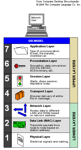
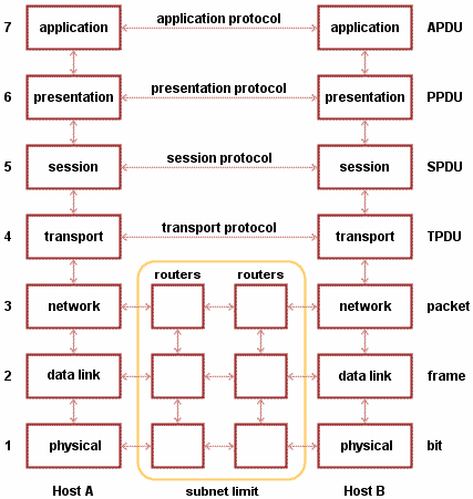
OSI divides telecommunication into seven layers. The layers are in two groups. The upper four layers are used whenever a message passes from or to a user. The lower three layers are used when any message passes through the host computer. Messages intended for this computer pass to the upper layers. Messages destined for some other host are not passed up to the upper layers but are forwarded to another host. The seven layers are:

Layer 7: The application layer ...This is the layer at which communication partners are identified, quality of service is identified, user authentication and privacy are considered, and any constraints on data syntax are identified. (This layer is not the application itself, although some applications may perform application layer functions.)

Layer 6: The presentation layer ...This is a layer, usually part of an operating system, that converts incoming and outgoing data from one presentation format to another (for example, from a text stream into a popup window with the newly arrived text). Sometimes called the syntax layer.

Layer 5: The session layer ...This layer sets up, coordinates, and terminates conversations, exchanges, and dialogs between the applications at each end. It deals with session and connection coordination.

Layer 4: The transport layer ...This layer manages the end-to-end control (for example, determining whether all packets have arrived) and error-checking. It ensures complete data transfer.

Layer 3: The network layer ...This layer handles the routing of the data (sending it in the right direction to the right destination on outgoing transmissions and receiving incoming transmissions at the packet level). The network layer does routing and forwarding.

Layer 2: The data-link layer ...This layer provides synchronization for the physical level and does bit-stuffing for strings of 1's in excess of 5. It furnishes transmission protocol knowledge and management.

Layer 1: The physical layer ...This layer conveys the bit stream through the network at the electrical and mechanical level. It provides the hardware means of sending and receiving data on a carrier.


Related Posts with Thumbnails