Popular Posts

Share |

Sunday, January 9, 2011

Lab guide - Lab 1-1: Cisco Remote Lab Connection

Following content has extracted from ICND (Interconnecting Cisco Networking Devices) Lab guide and added further clarifications where required for your convenience. **Important before start practicing, keep in mind that you would need a correctly wired and configured system as diagram unless some commands may not work correctly.


Complete this lab activity to practice what you learned in the related module.
Activity Objective
In this activity, you will Telnet to the terminal server to access the devices in your pod. After
completing this activity, you will be able to meet these objectives:
􀂄 Run Telnet to connect to the ICND remote lab
􀂄 Verify connectivity to the ICND remote lab terminal server
􀂄 Clear the connections to your workgroup switch and workgroup server


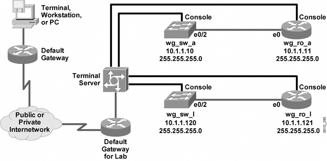
Visual Objective
The figure illustrates what you will accomplish in this activity.

Required Resources
These are the resources and equipment required to complete this activity:
􀂄 PC connected to an onsite laboratory or PC with an Internet connection to access the remote laboratory
􀂄 Terminal server connected to a console port of each laboratory device if using a remote laboratory
􀂄 ICND pod assigned by your instructor

Command List
The table describes the commands used in this activity.

Command 
telnet ip-address
Description
Starts a terminal emulation program from a PC, router, or switch that permits you to access network devices remotely over the network.

Task 1: Run Telnet to Connect to the ICND Remote Lab
To begin the lab activities, you will use the Telnet utility to establish a connection to the remote lab equipment for this course.

Activity Procedure
Complete these steps from your PC:
Step 1 From the Microsoft Windows Start menu, choose Run. The Run window appears.
Step 2 In the Open field, type the telnet command followed by the IP address for your
terminal server, provided by your instructor. For example, if the terminal server
address that your instructor provided is 10.1.1.254, you would type:
telnet 10.1.1.254
If your Telnet session successfully connects to the terminal server, you should see an
opening menu similar to the following:
**************************************************************
*******
CISCO ICND STUDENT MENU
CONNECT TO YOUR POD LETTER
**************************************************************
*******
ITEM# DEVICE NAME
--------------------------------------------------------------
-------
1 Connect to pod A
2 Connect to pod B
3 Connect to pod C
4 Connect to pod D
5 Connect to pod E
6 Connect to pod F
7 Connect to pod G
8 Connect to pod H
9 Connect to pod I
10 Connect to pod J
11 Connect to pod K
12 Connect to pod L
13 EXIT
Please enter selection:

Step 3 At the "Please enter selection:" prompt, enter your workgroup number and
press Return. Your output should look similar to the following:
***********************************************************
POD L
To exit back out to the menu press "CTRL+SHIFT+6" then "X".
You must clear the line before re-connecting to a device.
***********************************************************
1 Connect to workgroup switch L
2 Connect to workgroup router L
3 Clear connection to w/g switch L
4 Clear connection to w/g router L
5 Return to main menu
Please enter selection:

The menu, called the Pod menu, lists your pod letter at the top. In the example, the current pod is Pod L.
From the menu, you can connect to either your workgroup switch or your workgroup router.

Once you connect to a network device from the terminal server, you will need to use a special keystroke sequence, Ctrl-Shift-6, then x, to return to the menu. (To do this, hold down the Shift key, press the Ctrl key and the 6, then press the x key.)

Step 4 Enter 1 to connect to your workgroup switch. You should see the following (or something similar) in your Telnet session:

Please enter selection: 1
Trying h26 (10.10.10.10, 2058)... Open


Step 5 Press Return to access the device prompt.
Note Your output will vary depending on the switch type that you are connected to. On an
unconfigured Catalyst 2950 series switch, setup mode appears if no previous configuration
changes have been made.

Step 6 To return to the menu, enter Ctrl-Shift-6, then x. The Pod menu appears again. When you return to the Pod menu, your session to your workgroup switch is still open. You should clear all open connections on a terminal server before exiting. If you do not close your open sessions, the Cisco IOS software will prompt you to close your open connections. To close a session, you must select the appropriate
option from the menu.

Step 7 Enter option 3 to clear the connection to your workgroup switch. When the "[confirm]" prompt appears, press Return.

What does the prompt say now?

Step 8 Enter option 2 to connect to your workgroup router.
What does the prompt say now? As with the switch, you may need to press Return one time to see the prompt on your terminal screen.

Step 9 Enter Ctrl-Shift-6, then x, to return to the Pod menu.

Step 10 Enter option 4 to clear the connection to your workgroup router. When the "[confirm]" prompt appears, press Return.

Step 11 Enter option 5 to return to the Main menu from the Pod menu.

Step 12 Exit the terminal server by entering the option from the Pod menu to exit. If there is no option to exit on the menu, contact your instructor for instructions.

Step 13 If you see the "You have open connections [confirm]" prompt, enter yes and press Return. Depending on which operating system is running on your PC, you may need to press Return after terminating your Telnet session.

Step 14 Notify your instructor that you have completed the activity.

Activity Verification
You have completed this task when you attain these results:
􀂄 You can successfully log on to the terminal server and navigate the menus to access your workgroup switch and workgroup router
􀂄 You can clear the connections to your workgroup switch and workgroup router

Wednesday, December 1, 2010

Address Resolution Protocol (ARP)

What is ARP broadcast ?
A well known and common term ARP Broadcast in the network industry, is simply stands for Address Resolution Protocol. knowing the following terms are also will be helpful to understand the functions of this protocol.

Broadcast - Send to many
Multicast   - Send to many, but not to all
Unicast     - Send to specific destination

Address Resolution Protocol is a something to gather data about destination MAC address before starting to send data packets. The method to find out the destination's MAC address is send broadcast messages to all the connected devices with requesting their MAC addresses. As seems as the name, In the ARP broadcast, A data packet will be sent to the all connected devices within the network. The word "within the network" is important, because the ARP broadcast message will never go beyond the router. that usually means only in local network. 

There's a reason to not to allow ARP broadcasts beyond the router. because such messages are making remarkable traffic on network. Since the every drop of bandwidth is very precious on internet, such traffic making packets are restricted to go beyond router. 

Now let's see how is the Address Resolution Protocol is functioning.
we'll just consider the following scenario
Think that the HOST A wants to send some data to HOST B. But HOST A still don't know the MAC address of the HOST B. Then before starting to send data packets, The HOST A sends a ARP broadcast message to request the HOST B's MAC address. All devices in the local network receive the ARP and as same as HOST B is also receive the ARP Broadcast from HOST A because it's also in the same network. Then HOST B sends a uncast ARP reply message to HOST A including his MAC address. The word "unicast" is important because HOST B know where to send the reply and he directly send it to HOST A. After that the HOST A starting to send data to HOST B.

Let's look at a little bit different situation like this.
Think, in the above network, HOST A wanted to send some data to HOST B. But keep in mind the HOST A and HOST B are on different networks current situation because a router is in between them. You already know that the ARP broadcast messages are not passes through the router. 
Now what happen is, Router knows the HOST B's MAC address. when the ARP broadcast gets to the router, the router sends a message to the HOST A like this. "The ARP broadcast can't be allow through me, but the destination you are looking for may be outside the network. so, this is the MAC address of the default gateway (ethernet 0). please send data to here and I'll send them to the correct destination on behalf you."

Then the data transferring is taking place.

Important.
ARP messages are broadcasts
Successfully forwards through Switches and hubs
Not allow beyond or through router

Tuesday, August 17, 2010

TCP - Transmission Control Protocol

Windowing - Automatic Flow Control
Windowing - Automatic Flow Control, TCP - Transmission Control Protocol
Click on image if not clear
As we discussed about how a connection being established  between two devices in TCP ( please refer the topic  3 way handshake concept ), The next immediate step is to start transferring data packets. It just happen like this.

Step 1. Establishing Connection
A -->>-->>-->>-->>-- Synchronization -->>-->>-->>-->>-- B
A --<<--<<--Acknowledgement + Synchronization--<<--<<--
A-->>-->>-->>-->>--Acknowledgement-->>-->>-->>-->>--B
A ---<<--<<--<<---Connection  Established---<<--<<--<<---B

Step 2. Data Transferring
A -->>-->>-->>-->>-->>--Packet  1-->>-->>-->>-->>-->>--B
A--<<--<<--<<--<<--Acknowledgement 2--<<--<<--<<--<<--B
Remember that when B receives the packet number 1, B send Acknowledgement number 2 

A--->>-->>-->>-->>---Packet  2, 3, 4, 5--->>-->>-->>-->>---B
A--<<--<<--<<--<<--Acknowledgement   6--<<--<<--<<--<<--B
A->>-->>-->>---Packet 6, 7, 8, 9, 10, 11, 12, 13-->>-->>-->>-B
A--<<--<<--<<--<<--Acknowledgement 11--<<--<<--<<--<<--B
See the above incident, A sends packet number 6 to 13 but B sends the acknowledgement number 11. That means B has only received packets up to number 10. Then A have to send lost packets again.


A->>-->>-->>-->>---Packet 11, 12, 13, 14->>-->>-->>--->>--B
A--<<--<<--<<--<<--Acknowledgement  15--<<--<<--<<--<<--B

Likewise A always wants to finish sending packets as possible as early. So A gradually increase the number of packets sending in one time. But at a certain level B gets busy and fails to handle all the packets, Then B send a message to A to say that the number of packets sending in one time is too much, so please decrease the number of packets. Then A decrease the number of packets and in such case the data flowing rate is increasing and decreasing automatically. If you observe the data flowing rate via a graphical chart you can see the rate is going up and down like this.

Windowing - Automatic Flow Control, TCP - Transmission Control Protocol

This process calling windowing (automatic flow control) in TCP

Wednesday, August 11, 2010

Three way handshake Concept (3 Way handshake)

How a Connection establish in TCP/IP according to the Three way Handshake (3Way handshake) concept

Three way handshake Concept, TCP/IP, connection, Host PC, packets, synchronization
Three way handshake is regarding establishing a TCP socket connection between two pc's in three steps. It just happens like this. Assume that you have two pc's called host A and host B. They are connected physically with appropriate cables via Ethernet ports. TCP/IP protocol is running.

Step 1. Host A sends a synchronization packet to the Host B
just asking "Hello friend, I would like to establish a connection with you. Would you like ?

Step 2. Host B replies to Host A with a Acknowledgement packet + synchronization packet   
Acknowledgement packet says that "Yes I like to establish a connection with you" and Synchronization packet says "Please confirm it"

Step 3. Host A sends an Acknowledgement packet to Host B 
To say that " OK, then we'll establish a connection"

This is how a connection establish with 3way handshake (Threeway handshake) concept

Then three way handshake CONNECTION ESTABLISHED and starts to flow data between two hosts. In next post we'll see how the data flowing taking place between two hosts and controlling flow by them self. think all are very clean and clear here and you enjoyed it. 

Friday, April 9, 2010

Rapid Spanning Tree Protocol - 802.1d

RSTP bridge port roles:
Root - A forwarding port that is the best port from Nonroot-bridge to Rootbridge
Designated - A forwarding port for every LAN segment
Alternate - An alternate path to the root bridge. This path is different than using the root port.
Backup - A backup/redundant path to a segment where another bridge port already connects.
Disabled - Not strictly part of STP, a network administrator can manually disable a port

RSTP is a refinement of STP and therefore shares most of its basic operation characteristics. However there are some notable differences as summarized below:

Detection of root switch failure is done in 3 hello times, which is 6 seconds if default hello times have not been changed.

Ports may be configured as edge ports if they are attached to a LAN that has no other bridges attached. These edge ports transition directly to the forwarding state. RSTP still continues to monitor the port for BPDUs in case a bridge is connected. RSTP can also be configured to automatically detect edge ports. As soon as the bridge detects a BPDU coming to an edge port, the port becomes a non-edge port.

Unlike in STP, RSTP will respond to BPDUs sent from the direction of the root bridge. An RSTP bridge will "propose" its spanning tree information to its designated ports. If another RSTP bridge receives this information and determines this is the superior root information, it sets all its other ports to discarding. The bridge may send an "agreement" to the first bridge confirming its superior spanning tree information. The first bridge, upon receiving this agreement, knows it can rapidly transition that port to the forwarding state bypassing the traditional listening/learning state transition. This essentially creates a cascading effect away from the root bridge where each designated bridge proposes to its neighbors to determine if it can make a rapid transition. This is one of the major elements that allows RSTP to achieve faster convergence times than STP.

As discussed in the port role details above, RSTP maintains backup details regarding the discarding status of ports. This avoids timeouts if the current forwarding ports were to fail or BPDUs were not received on the root port in a certain interval.

Tuesday, March 23, 2010

802.1d - How the STP functioning ?

Function of Spanning Tree Protocol - 802.1d
At the first I think it's better to have a brief description on STP.

STP is directly responsible for avoid following errors occur in a switched network, where the switches are connected in a loop.

1. Avoid receiving multiple frames of same data to hosts
2. Avoid packets going on an endless loop
3. Make MAC address table steady 

all of above errors are possible to occur in an environment where the STP in not available. STP blocks a selected port on a loop to avoid those errors. The blocking port selected as follows.

STP blocks the designated port of highest cost path bearing switch to the root bridge. Then what are the designated ports and root bridge ?

Bridge ID, BPDU and Root bridge

Every switch has a bridge ID. Bridge ID is a combination of Priority value and lowest MAC address value. Priority value is 32768 by default in catalyst switches and it could be configure manually. The first factor is to consider for bridge ID is priority value. If the value is low, Bridge ID is high. value 1 is the maximum and value 0 is not be consider. If some switches have same priority, then the MAC address will be considered. Lower the MAC address is higher the Bridge ID. 

Scene 1
In every 2 seconds, every switch send a packet named BPDU ( Bridge Protocol Datagram Unit ) which includes details about bridge ID and etc. By BPDU's every switch came to know about all other switch's Bridge IDs and they automatically appointed a leader switch which have the highest Bridge ID ( Highest priority and lowest MAC ). The leader is named as Root bridge.

Scene 2
After appointing a root bridge the switches mark their ports as following
1. Root port - Outgoing port towards the root bridge
2. Designated port - Other ports in the loop except Root port

Scene 3
Calculate the costs of paths as follows
                    old      new
10Gbps                   2
01Gbps        1         4
100Mbps     10       19
10Mbps       100     100

After that the STP blocks the designated port at the port where the highest cost path to the root bridge. Then the loop will no available any more. Remember that the BPDU's can go through blocked port while other packets can't. 

Scene 3 
let's see what will happen when a link to the root port is went down. Remember that the STP can keep a port on 4 modes as follows
1. blocking
2. listening
3. learning
4. forwarding

When a link to the root bridge is down the blocked port have to come up for the proper functioning of the network. Bringing a port to the forwarding mode happen as follows

step 1. when a link is down the switch will not receive anymore BPDU's from that side. In certain cases a switch may miss some BPDUs. because of that switch stay for 20 seconds ( 10 BPDU ) to exactly know whether the link is down. If no any BPDU received from that side for 20 seconds, then the switch know exactly there's a problem.

step 2. After 20 seconds the port will be changed the status in to listening mode. in listening mode, the switch send BPDU's through the blocked port and listen do they come back from the other side. That's to make sure that there will not occur any loops if the blocked port is opened. The port keep on listening mode for 15 seconds and then go to the next step if there's no BPDU receiving from the other side.

step 3. Then the port will change the status to learning mode where the switch learns MAC addresses of network. Stay another 15 seconds on learning mode

step 4. The port will be opened for packets and start forwarding.

like that in STP it takes minimum of 50 seconds to network bring back to functioning. It is a big disadvantage taking so much time to bring the network up and working. All of the above described mode changing activities can be observe in a real switched network or by using Packet tracer with some techniques. For packet tracer users, I can send a simulation file on your request. please leave a comment or send a message via facebook if you need those simulation files.

Tuesday, March 16, 2010

Spanning Tree Protocol - 802.1d

Overview and introduction to Spanning tree protocol
STP is a standard protocol which is works on any brand of switches. ISL ( Inter Switch Link ) is the Cisco proprietary protocol instead of STP. STP cannot be explained alone since it's related with several number of operations on switches such as Bridge ID, BPDU and etc.


Spanning-Tree Protocol (STP) as defined in the IEEE 802.1D is a link management protocol that provides path redundancy while preventing undesirable loops in the network. For an Ethernet network to function properly, only one active path can exist between two stations. Loops occur in networks for a variety of reasons. The most common reason you find loops in networks is the result of a deliberate attempt to provide redundancy - in case one link or switch fails, another link or switch can take over.

STP is a technology that allows bridges to communicate with each other to discover physical loops in the network. The protocol then specifies an algorithm that bridges can use to create a loop-free logical topology. In other words, STP creates a tree structure of loop-free leaves and branches that spans the entire Layer 2 network.

Spanning-Tree Protocol operation is transparent to end stations, which are unaware whether they are connected to a single LAN segment or a switched LAN of multiple segments. Where two bridges are used to interconnect the same two computer network segments, spanning tree is a protocol that allows the bridges to exchange information so that only one of them will handle a given message that is being sent between two computers within the network.

Bridge Protocol Data Units (BPDUs) is used by bridges in a network to exchange information regarding their status. The Spanning-Tree Protocol uses the BPDU information to elect the root switch and root port for the switched network, as well as the root port and designated port for each switched segment.

The program in each bridge that allows it to determine how to use the protocol is known as the spanning tree algorithm, which is specifically constructed to avoid bridge loops. The algorithm is responsible for a bridge using only the most efficient path when faced with multiple paths. If the best path fails, the algorithm recalculates the network and finds the next best route. 
The spanning tree algorithm determines the network (which computer hosts are in which segment) and this data is exchanged using Bridge Protocol Data Units (BPDUs). It is broken down into two steps:

Step 1: The algorithm determines the best message a bridge can send by evaluating the configuration messages it has received and choosing the best option.


Step 2: Once it selects the top message for a particular bridge to send, it compares its choice with possible configuration messages from the non-root-connections it has. If the best option from step 1 isn't better than what it receives from the non-root-connections, it will prune that port. 

Monday, March 15, 2010

Lab commands - VTP configurations

How to Configure VTP and how to view configurations ?
Since you have practiced certain commands and been in touch with cisco devices i assume that i don't need to explain basic commands from here.
As you know by default all the Catalyst switches are on server mode. To view the current mode,
in CLI ( Command Line Interface )
go to privilege mode enter following command.

Switch#show vtp status 
VTP Version                     : 2
Configuration Revision       : 0
Maximum VLANs supported locally : 255
Number of existing VLANs              : 5
VTP Operating Mode                       : Server
VTP Domain Name                          : 
VTP Pruning Mode                          : Disabled
VTP V2 Mode                                : Disabled
VTP Traps Generation                     : Disabled
MD5 digest                      : 0x7D 0x5A 0xA6 0x0E 0x9A 0x72 0xA0 0x3A 
Configuration last modified by 0.0.0.0 at 0-0-00 00:00:00
Local updater ID is 0.0.0.0 (no valid interface found) 

You can see the VTP operating mode is Server and many details which we have to discuss in advance.

Now enter to Global configuration mode and type following commands


Switch(config)#vtp mode client " To change the VTP mode from server to client "
Setting device to VTP CLIENT mode.
Switch(config)#vtp domain cisco " To assign the domain name as cisco "
Changing VTP domain name from NULL to cisco

As i explained in earlier articles, the domain name must be same in all switches which you want to make receive updates from a server switch. That meant when you assign domain name as cisco for one switch in server mode and assign all other client mode switched the sane domain name, All client switches which have domain name as cisco will receive updates from server switch.

Saturday, March 13, 2010

Lab commands - VLAN configurations

Lab commands - VLAN configurations


Switch#enable "enter to privilage mode"


Switch#configure terminal  "Enter to Global configuration mode"


Enter configuration commands, one per line.  End with CNTL/Z.


Switch(config)#interface vlan 1 "Go to interface mode of VLAN 1"


Switch(config-if)#ip address 10.1.1.1 255.255.255.0 "Assign IP address for interface VLAN 1 with the subnet mask"


Switch(config-if)#no shutdown "make the interface up"


%LINK-5-CHANGED: Interface Vlan1, changed state to up
Switch(config-if)#
%SYS-5-CONFIG_I: Configured from console by console
Switch#


VIEW CONFIGURATIONS


Switch#show interfaces VLAN 1 "Show details of  interface VLAN 1"
Vlan1 is up, line protocol is down "Both vlan1 and line protocol must be up for working condition"


Hardware is CPU Interface, address is 0010.1116.ce76 (bia 0010.1116.ce76)
  Internet address is 10.1.1.1/24
  MTU 1500 bytes, BW 100000 Kbit, DLY 1000000 usec,
  reliability 255/255, txload 1/255, rxload 1/255
  Encapsulation ARPA, loopback not set
  ARP type: ARPA, ARP Timeout 04:00:00
  Last input 21:40:21, output never, output hang never
  Last clearing of "show interface" counters never
  Input queue: 0/75/0/0 (size/max/drops/flushes); Total output drops: 0
  Queueing strategy: fifo
  Output queue: 0/40 (size/max)
  5 minute input rate 0 bits/sec, 0 packets/sec
  5 minute output rate 0 bits/sec, 0 packets/sec
     1682 packets input, 530955 bytes, 0 no buffer
     Received 0 broadcasts (0 IP multicast)
     0 runts, 0 giants, 0 throttles
     0 input errors, 0 CRC, 0 frame, 0 overrun, 0 ignored
     563859 packets output, 0 bytes, 0 underruns
     0 output errors, 23 interface resets
     0 output buffer failures, 0 output buffers swapped out


Switch#SHOW running-config "view running configurations of interface VLAN 1"

!
interface Vlan1
 ip address 10.1.1.1 255.255.255.0
!

Friday, March 12, 2010

Test Inside 640-802 (CCNA Exam Simulator)

DOWNLOAD NOW FOR FREE....
“CCNA ’s Cisco Certified Network Associate”, also known as 640-802 exam, is a Cisco certification. Preparing for the 640-802 exam? Searching 640-802 Test Questions, 640-802 Practice Exam, 640-802 Dumps? With the complete collection of questions and answers, TestInside has assembled to take you through 252 questions to your 640-802 Exam preparation. In the 640-802 exam resources, you will cover every field and category in CCNA helping to ready you for your successful Cisco Certification.


Password - careercert.blogspot.com
Related Posts with Thumbnails